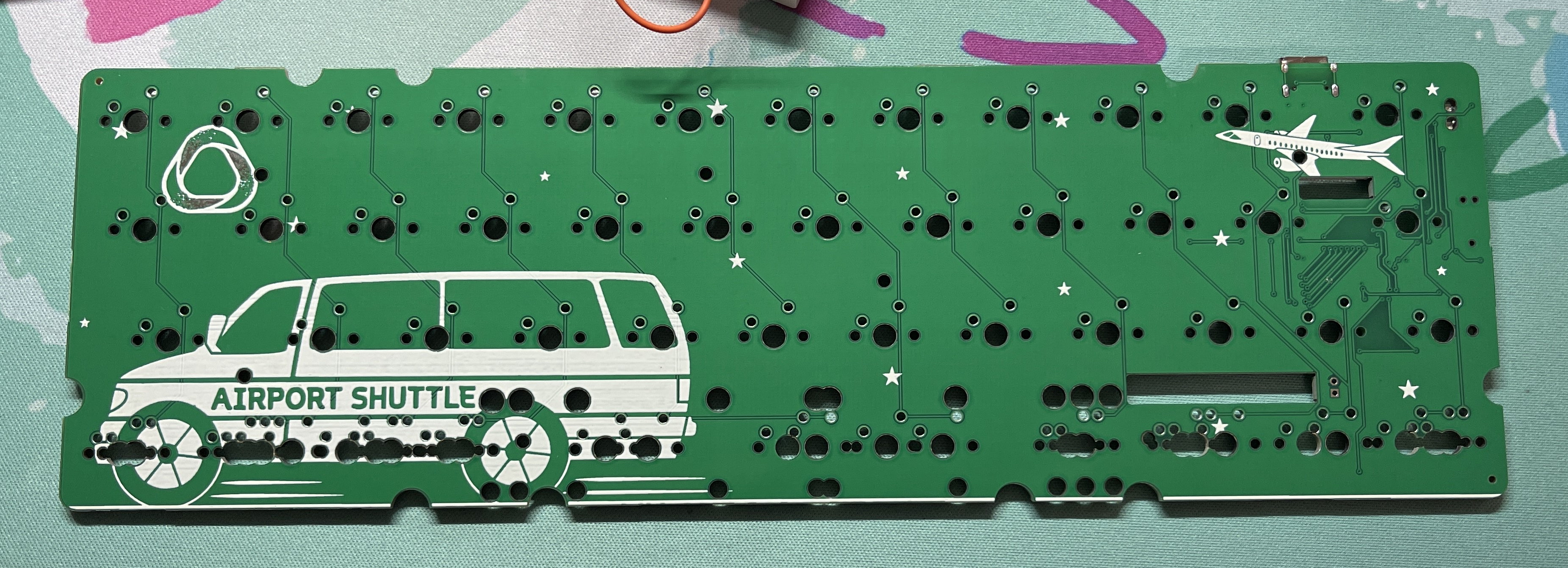
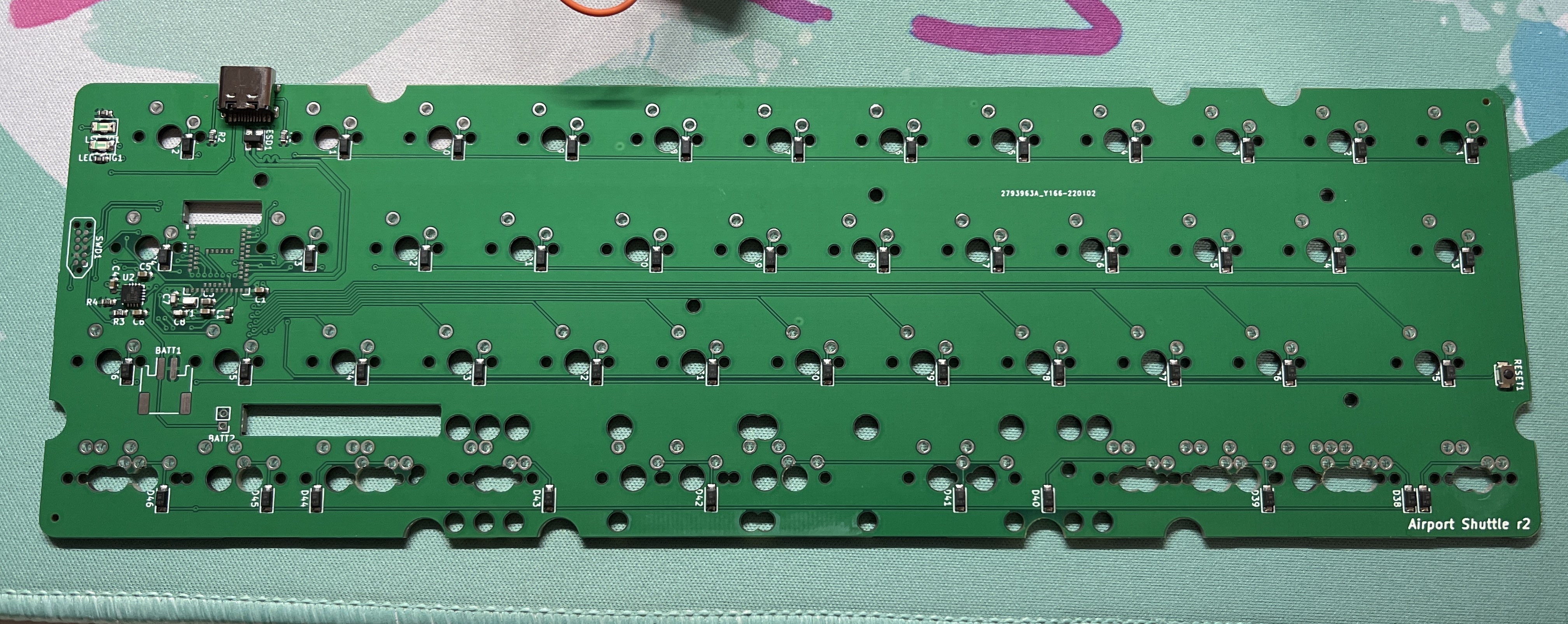
Airport Shuttle is a Bluetooth-powered MiniVan-compatible PCB designed by Aeternus.
Two small, private group buys were run for v1 and v1.75 PCBs. A larger public group buy for v2 PCBs ran in March 2022 at Aeternus.co. PCBs were available for $80 each. Bluetooth dongles and batteries were available as optional add-ons.
Discussion about Airport Shuttle can be found in the #airport-shuttle in Aeternus's Discord server.
¶ Design
Check the MiniVan Compatibility Matrix for case compatibility
| Designer | Aeternus |
|---|---|
| Compatibility | MiniVan |
| Firmware | ZMK source |
| Layouts | Rev 1: KLE link |
| Rev 1.75: KLE link | |
| Plate files | DXFs on the Files page |
| Switches | Soldered MX |
| 4x rotary encoder (rev 1.75) | |
| LEDs | 2x battery indicators (rev 2) |
| Connection | Integrated USB-C |
| Bluetooth | |
| Controller | EBYTE E73 (rev 1/1.75) |
| Raytac MDBT50 (rev 2) |
The backside of the PCB includes all of the soldered components, including the integrated MCU+Bluetooth module chip. The PCB operates wirelessly when powered by a small 3.7v lithium polymer battery. A charging circuit for the battery is connected to the USB C port. The USB port was located in the top-right corner and 7 mounting holes were included to to ensure compatibility with MiniVan cases.
The board runs ZMK firmware (rather than the traditional QMK firmware) because the GPL-licensed QMK firmware prevents the inclusion and distribution of the closed-source SDKs for Bluetooth modules. ZMK uses the MIT license and as such does not have these restrictions for distribution.
¶ Battery
301230batteries can be found on most sites that sell nice!nano PCBs like KeyHive and Clawsome
Airport Shuttle was designed to use a 301230 lithium polymer battery. This size was chosen as it can fit between the PCB and case bottom without interfering with switch pins. v1.75 and v2 PCBs feature cutouts in the board for additional battery clearance.
After prototype rev 1.0 units were sent out it was discovered that many users had a hard time fitting batteries underneath the PCB in standard tray mount MiniVan cases. As a result, Trash Man and Aeternus created a modified Rackmount case that includes cutouts in the bottom to increased clearance for the Bluetooth module and a large battery. The battery well is sized to accommodate a large 2500 mAh LiPo battery (model 375678) that Trash Man owned: LINK
¶ Bluetooth Dongle
The approved Bluetooth dongle for use with Airport Shuttle is available from Adafruit: https://www.adafruit.com/product/5199
Some users (particularly on Windows systems) have experienced poor connection reliability with their Airport Shuttles. While later revisions include modifications to improve the Bluetooth signal, the connectivity issues are often compounded by installation in metal cases. Through testing it was determined that connecting the keyboard to a programmable USB Bluetooth dongle resolved nearly all connectivity issues and resulted in greatly improved battery life.
The dongle communicates directly with the keyboard via Bluetooth and presents itself to the host computer as a wired USB keyboard. This allows the PCB to be used wirelessly while completely bypassing the computer's Bluetooth stack. In addition, the estimated battery life with a 100mAh 301230 battery improved from roughly 2 weeks to over 4 months.
¶ Layout
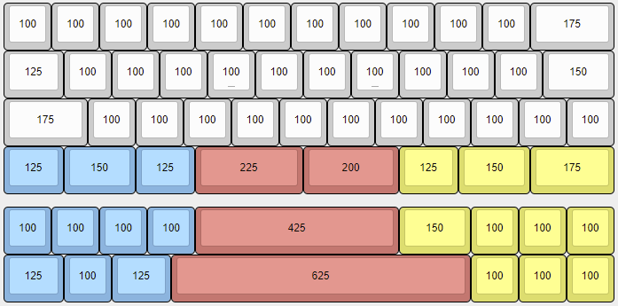
Both revisions of Airport Shuttle support all common MiniVan layouts as well as 425 spacebar and Jetvan layout.
¶ Rev 1.0
¶ Rev 1.75
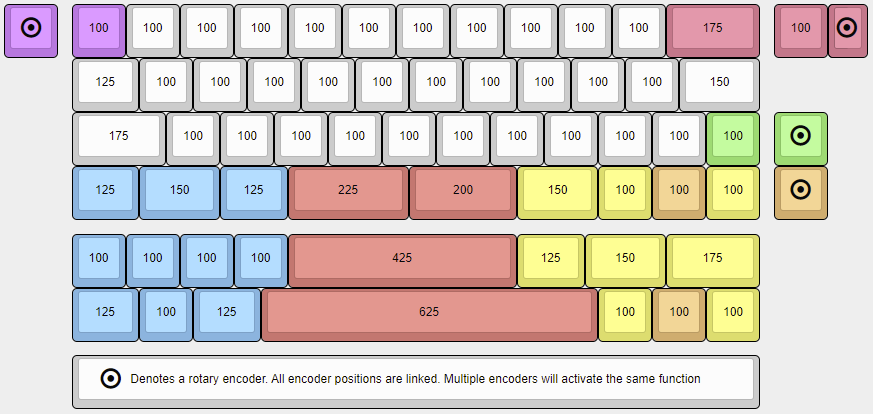
Revision 1.75 adds support for several rotary encoder locations. While multiple encoders can be physically installed, all encoder positions are wired together and activate the same function when operated. The encoder positions are:
- top-left corner (Esc)
- split 1u + encoder knob in the top right (Backspace)
- key to the right of the arrow cluster (below Enter)
- the "down arrow" in the Arrows layout
¶ Rev 2.0
R2 PCBs add a few new layouts, including 2x3u spacebars and a WKL layout.
¶ Revisions
¶ Rev 1.0
Rev 1.0 PCBs were considered prototypes for testing the Bluetooth module and firmware. Only a handful of the original prototype PCBs were produced and sold to early adopter community members.
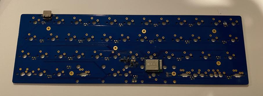
The backside of the PCB includes all of the soldered components including the integrated Bluetooth module located above the spacebar switch. Two small through-hole pads to the left of the Bluetooth module allowed for wires to be soldered for a 3.7 volt lithium-polymer battery to allow wireless operation. An integrated circuit enabled the board to recharge the battery when plugged into a host or other power source via the USB C port. The USB port is located in the top-right corner and tray mount holes were included to to ensure compatibility with MiniVan cases.
All switch positions were south-facing with the exception of the left split spacebar which had to be flipped to make space for the Bluetooth module. PCB-mount stabilizer holes were included for both split spacebars and a 6.25u spacebar to support the JetVan layout. There were no holes for in-switch LEDs or surface-mount LEDs anywhere on the board.
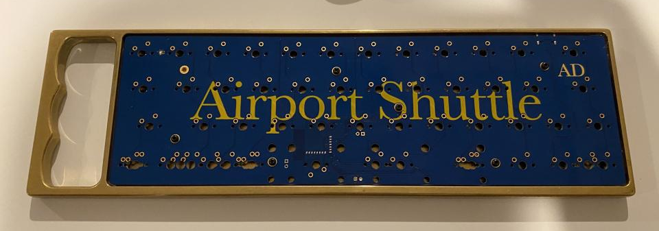
The front of the initial PCBs featured the name of the board silkscreened in gold against a blue solder mask. The letters "AD" were included in the top-right corner below the backspace switch position.

¶ Rev 1.75
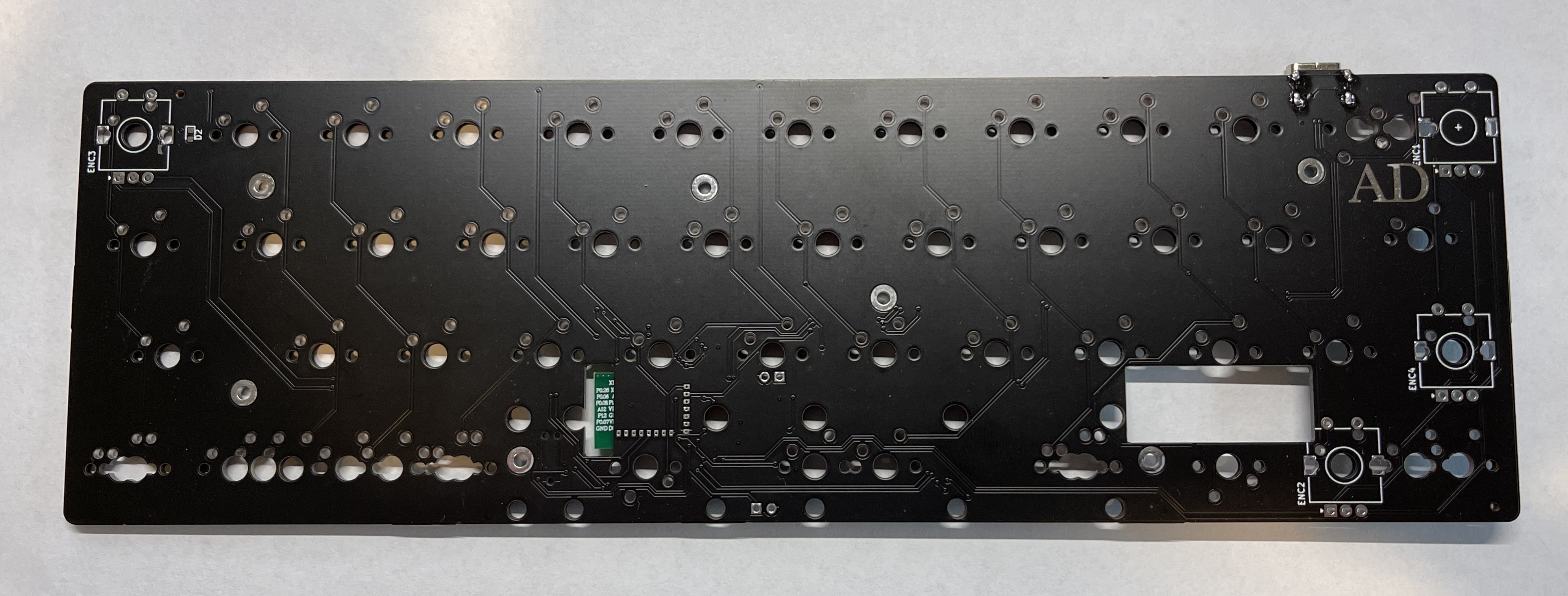
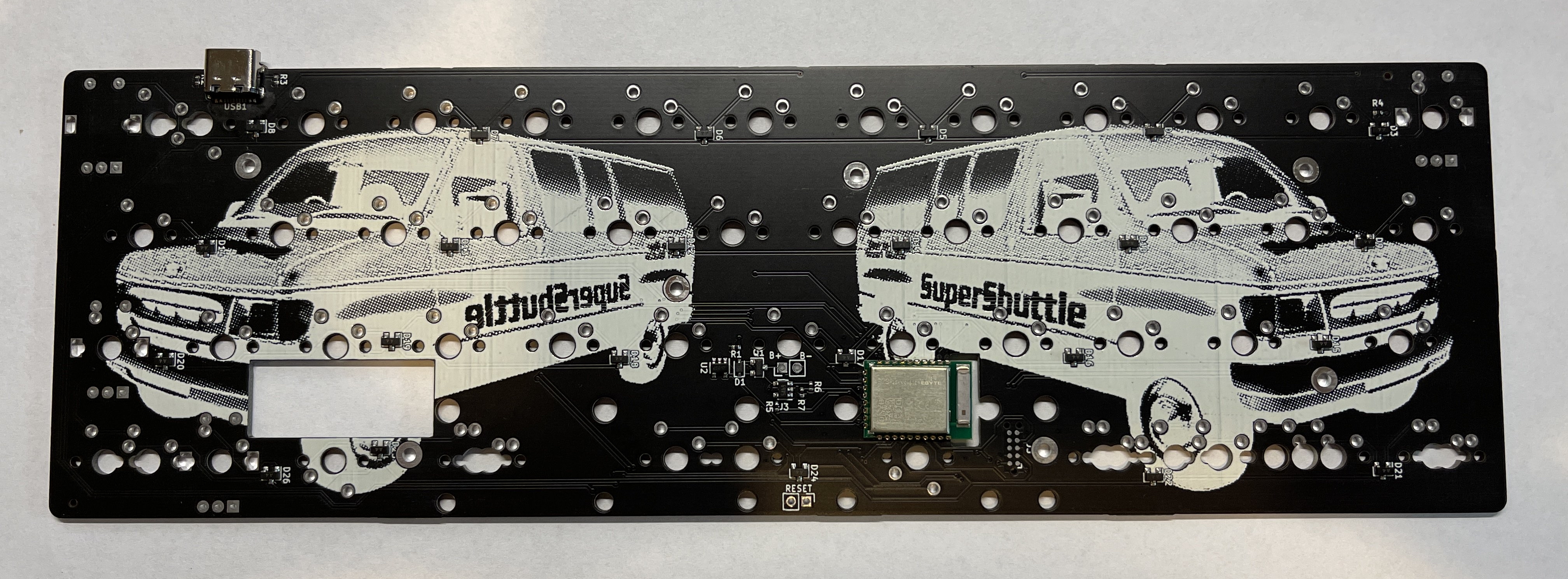
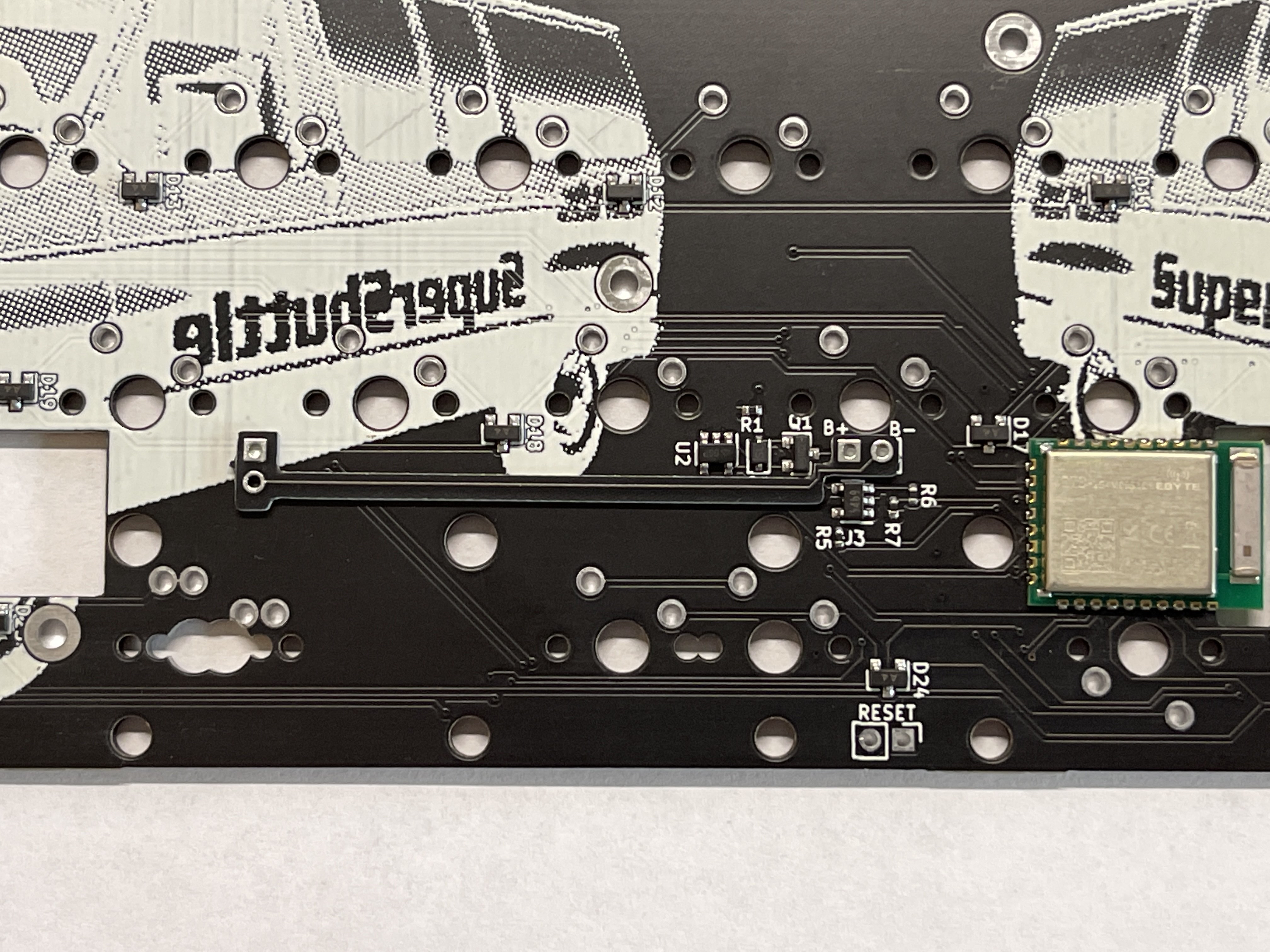
The updated revision 1.75 PCBs adds support for rotary encoders in several locations. A cutout is situated underneath the Bluetooth module to provide better signal integrity for the antenna (the R1 PCB had no copper fill in this area but still had PCB material). A 12mmx30mm cutout is located between the spacebar and arrow cluster to provide space to install a small battery in cases that do not have enough clearance below the PCB. The largest battery that will fit in the cutout is a 301230 lithium polymer battery.
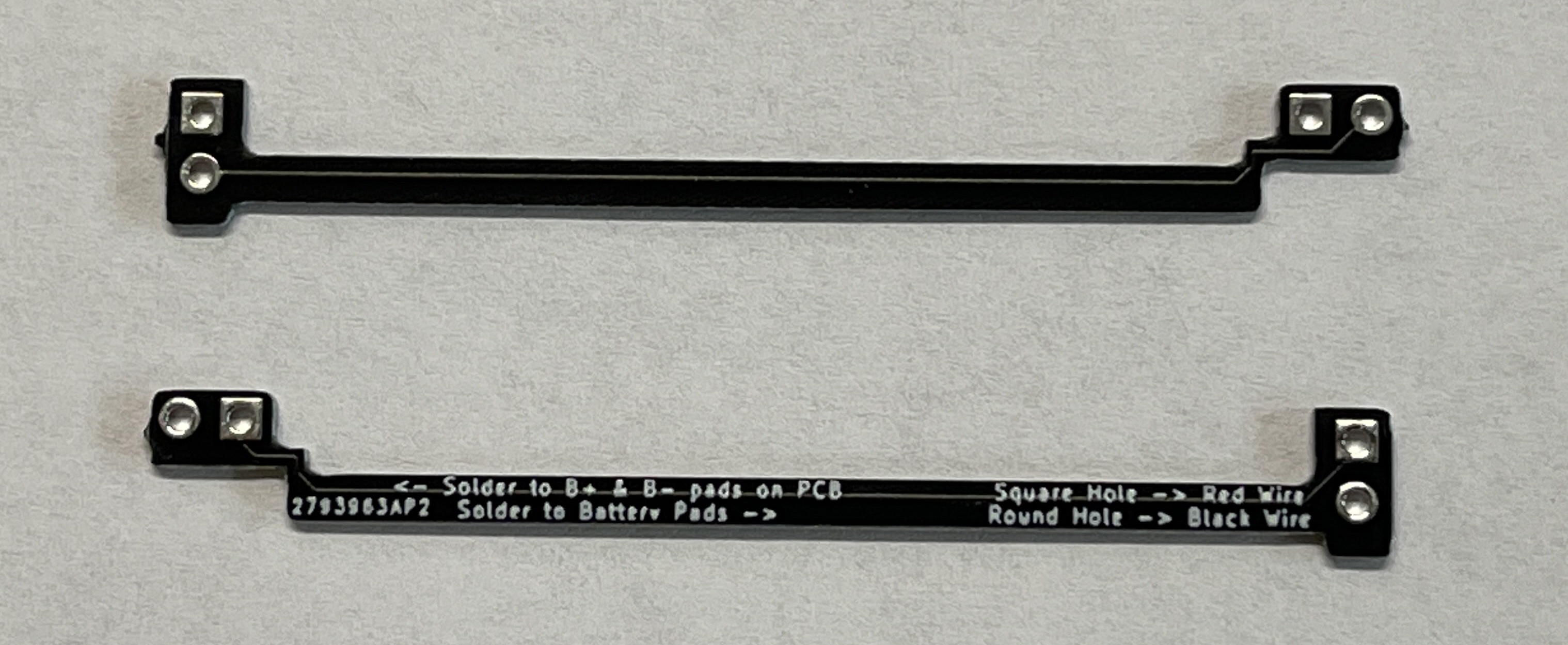
Many of the small batteries that will fit in the battery cutout do not have long enough included leads to reach the battery solder points in the middle of the PCB (below the B key). To assist with installation a small PCB was created that can be soldered to the battery pads on the PCB and extends toward the battery cutout. This extra PCB was included with every order.
In order to improve the durability of the USB connector, a small portion of the PCB extends out below the connector to reinforce the solder anchors. Unfortunately, this tiny extra PCB section causes interference with many cases that have tight-fitting USB-C cutouts, such as plastic tray-mount cases and MHKB.
¶ Rev 2.0
Aeternus has shared images of prototypes for an R2 PCB. The board features several new bottom row layouts, a smaller and repositioned Bluetooth module, and a smaller battery cutout. The battery cutout on R2 PCBs is 32mm x 5mm and is designed to hold the battery standing vertically while still fitting under the switch plate in most cases. This change prevents interference with several bottom row switches that had to be rotated on R1.75 boards. The battery +/- pads on the PCB are relocated next to the cutout to ensure that batteries with short leads can still be connected. Pads for a 2-pin JST header are included if users wish to solder on a detachable connector for their battery.
Two LEDs are located in the top-right corner of the PCB under the Backspace key. One functions as a charging indicator and the other is available as a general purpose LED. A RESET button is located along the right edge on the back of the PCB. This location ensures compatibility with the reset hole on many MiniVan cases.
New cutouts along the edges of the board enable compatibility with upcoming Aeternus cases.
